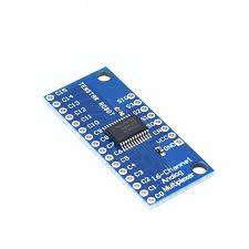
Features “On” resistance: 70 Ohms @ 4.5V 6ns break-before-make @ 4.5V On the electronics module there are 2 rows of header solder points. These can be used to connect wires to or header pins depending on the application. 1×8 Header Location SIG = Signal Input / Output. This will usually connect to an analog input or digital I/O on the microcontroller S3 = Binary Address Bit 3. The address bits (3…0) connect to 4 digital output pins on the microcontroller to select channel. S2 = Binary Address Bit 2 S1 = Binary Address Bit 1 S0 = Binary Address Bit 0 EN = Enable. Internally pulled LOW to enable by default. Can be pulled HIGH to disable all channels. VCC = 2 to 6V. Usually connected to 5V or 3.3V to match the microcontroller power. GND = Ground, must be common with the microcontroller. 1×16 Header Location C15 = Channel 15 C0 = Channel 0